


- 1
- 2
- 3
- 4
- ���F�ڵ�λ�ã� ��EDA�W >> CST >> CST�OӋ���� >> ����
CST�C��ǻ�w�OӋ������CST2013�OӋ����
�O�ù���ƽ�����
��ģǰ��Ҫ�O�ù���ƽ���С�����㽨ģ�������x�� View: Visibility ![]() Working Plane
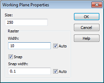
Working Plane ![]() Working Plane Properties ������_����ƽ����Ԍ�Ԓ��ģ�����ߴ���215���ף��@���O��һ��250���״�С�Ĺ���ƽ�������ˡ��ڌ�Ԓ���Size�ݔ��250�O�ù���ƽ���С������Width�ݔ��10�O�ÖŸ��С���O����ɺ��������O��ֵҲ���@ʾ���Ñ�����Ġ�B�ڡ�
Working Plane Properties ������_����ƽ����Ԍ�Ԓ��ģ�����ߴ���215���ף��@���O��һ��250���״�С�Ĺ���ƽ�������ˡ��ڌ�Ԓ���Size�ݔ��250�O�ù���ƽ���С������Width�ݔ��10�O�ÖŸ��С���O����ɺ��������O��ֵҲ���@ʾ���Ñ�����Ġ�B�ڡ�
��ģ����
After these preparatory steps have been completed, you can now start drawing the figure of rotation. Because the cross section profile is a simple polygon, you do not need to use the curve modeling tools here (please refer to the Workflow and Solver Overview manual for more information on this advanced functionality). For polygonal cross sections, it is more convenient to use the figure of rotation tool, activated by selecting Modeling: Shapes ![]() Extrusions
Extrusions ![]()
![]() Rotate
Rotate ![]() .
.
|
Point |
X |
Y |
|
1 |
0 |
0 |
|
2 |
210 |
0 |
|
3 |
210 |
65 |
|
4 |
129 |
65 |
|
5 |
179 |
139 |
|
6 |
179 |
190 |
|
7 |
148 |
215 |
|
8 |
0 |
215 |
|
9 |
0 |
0 |
After the last point has been entered, the polygon will then be closed. The Rotate Profile dialog box will then automatically appear.
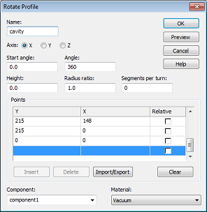
This dialog box allows you to review the coordinate settings in the table. If you encounter any mistakes you can easily change the values by double-clicking on the incorrect coordinates entry field.
The next step is to assign a specific Component and a Material to the shape. In this case, the default settings with component1 and Vacuum are practically appropriate.
Finally, you should assign a proper Name (e.g. cavity) to the shape and press the OK button in order to create the solid.
Smart Pick ![]() and Blend Edge
and Blend Edge ![]()
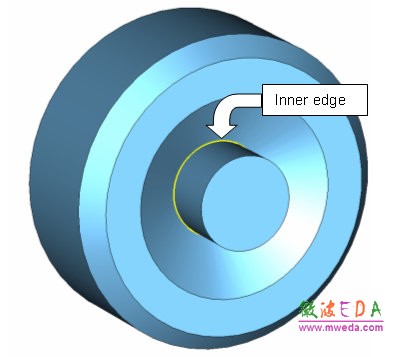
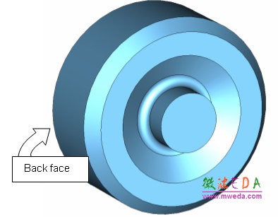
Sharp edges inside cavities are best avoided because strong field singularities will occur at these edges. Therefore, the sharp inner edge (shown on the picture below) should be blended.
The first step towards blending the edge is to pick the edge in the model by entering the smart pick mode via Modeling: Picks ![]() Picks
Picks![]() (shortcut S) in the main view window. Once this mode is active, which is indicated by edges and points in the model being highlighted, you can easily double-click at the inner edge. If the edge is hidden, you can rotate the view using the view changing tools as explained in the Workflow and Solver Overview manual. Sometimes it is also advantageous to switch the drawing mode to wireframe by selecting View: Visibility
(shortcut S) in the main view window. Once this mode is active, which is indicated by edges and points in the model being highlighted, you can easily double-click at the inner edge. If the edge is hidden, you can rotate the view using the view changing tools as explained in the Workflow and Solver Overview manual. Sometimes it is also advantageous to switch the drawing mode to wireframe by selecting View: Visibility ![]() Wire Frame
Wire Frame ![]() , or use the corresponding shortcut Ctrl+w.
, or use the corresponding shortcut Ctrl+w.
Once the proper edge has been selected, the model should look as follows:
If you accidentally picked the wrong edge, you can delete all picks using Modeling: Picks > Clear Picks (shortcut d) and try again.
The next step is to blend the selected edge. Therefore, press Modeling: Tools > Blend . Afterwards, a dialog box will open where you can set the Radius of the blend to 15 mm.
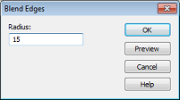
Finally press the OK button to apply the blend. The structure should then look as follows:
-
CST����ҕ�l�̳̣��Y����v�⣬ҕ�l������ʾ���Ļ��A�v��ѭ��u�M�����Y�����¹��̰������������ٌW������CST���OӋ����...��Ԕ����B��
- CST�쾀�OӋ���쾀��OӋ��CST2013�OӋ����
CSTͬ�S�������ķ����OӋ������CST2013�OӋ��
ʹ��CST���������M��TDRӋ�����
CST�cMatlab�B���O��
CST�������Һ�Agilent ADS �fͬ�����B���O��
CST�������Ҳ鿴VSWR�Y��
CST��������Y������c�ⲿ�����M�б��^
CST�������Ҳ��õ���Ҫ�㷨
ʹ��CST�������ҵĕr�����������늴��}��
늴ż��ݵĔ�ֵ�����������CST2013
CST�������ܺͷ��漼�g
CST�OӋ�h�� �� CST2013
���]�n��

-

7������ҕ�l�̳�,2���̲�,�Әӽ���
-

����������������ADS��Ӗ�̳����b
-

��ȫ��������l�����OӋ��Ӗ�ϼ�
-

Ansoft Designer �W����Ӗ�n�����b
����Ansoft Designer������Ӗ�̲�
-
ʸ�W,�l�V�x,��̖Դ...,�ӘӾ�ͨ
-

�c�I���B�Ӿo�ܵ��n��,�W������...
-

�I���ţLes Besser����Ӗ�n��...
-

Allegro,PADS,PCB�OӋ,�䌍�ܺ���..
-

Hyperlynx,SIwave,�����QSI���}
-

�F���v��,���r����,�����W���ɲ��`